


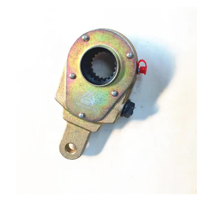
Sinotruk Howo Chassis Parts- Front Brake Adjusting Arm AZ9100440005
Basic information
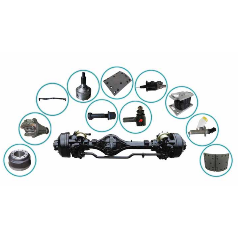
JCHHR supply full range SINOTRUK, HOWO, HOWO PART, HOWO SPARE PARTS,STEYR, WEICHAI,WABCO, WABCO VALVES, WABCO BRAKE PART, SHACMAN, SHACMAN F2000 PARTS, SHACMAN F3000 PARTS, SINOTRUCK, SITRAK spare parts,professional service and good price
HOWO spare parts,HOWO dump truck parts,Original HOWO parts,HOWO truck parts,HOWO A7 truck spare parts,Genuine HOWO truck parts,Original HOWO spare parts,HOWO 371 truck spare parts,
HOWO part, HOWO tipper truck, HOWO 336, HOWO 371, HOWO concrete mixer, HOWO 70T,HOWO 70T mining truck parts, HOVA, HOVA 60, HOVA mining truck, HOVA parts, HOVA 60T, STEYR WD615,Original STEYR spare parts, STEYR 91 series, STEYR dump truck, STEYR WD618, WEICHAI,Original WEICHAI parts, Genuine WEICHAI part, WEICHAI spare parts, WEICHAI WD615, WEICHAI WP10, WEICHAI WP12, WD615,WD615 engine parts, WD615.47, WD615.69, WD615 336hp, WD615 371hp, WD618 diesel engine parts, WD618 420hp, D10 engine parts, D12 engine parts.
Specifications
|
PRODUCT NAME |
Front Brake Adjusting Arm |
OE NO. |
AZ9100440005 |
BRAND NAME |
SINOTRUK Howo |
|
MODEL NUMBER |
AZ9100440005 |
TRUCK MODEL |
WP10, WP12, WP6, WP7, WP5, WP4, WP3, WD615, WD618 |
PLACE OF ORIGIN |
Shandong, China |
|
SIZE |
Standard Size |
CERICATION |
CCC |
APPLICABLE |
Howo |
|
FACTORY |
CNHTC SINOTRUK |
TYPE |
BELT |
MOQ |
1pc |
|
APPLICATION |
ENGINE SYSTEM |
QUALITY |
High-Performance |
MATERUAK |
Rubber |
|
PACKING |
Standard Package |
SHIPPING |
By sea, By air |
PAYMENT |
T/T |
Relevant Knowledge
Simple judgment method of adjusting arm:
1. Check the material and mechanical strength of the adjusting arm shell and internal accessories;
2. Rotate the hexagon of the worm screw of the first-generation adjusting arm assembly continuously counterclockwise for 30 circles. During the rotation process, failure phenomena such as slipping, jumping teeth, and breaking are not allowed. After 30 circles of rotation, the locking torque of the adjusting arm must be maintained. Above 20N.m;
3. Rotate the hexagon of the worm screw of the second-generation adjusting arm assembly continuously counterclockwise for 50 circles. During the rotation process, failure phenomena such as slipping, jumping teeth, and breaking are not allowed. After 50 circles of rotation, the locking torque of the adjusting arm must be Keep above 25N.m;
Failure judgment of the front axle brake adjustment arm:
1. Appearance judgment:
Check the shell and control arm and other parts, and judge the failure of the products with cracks or breaks. Products with severe wear on the reinforcing ring and connecting sleeve shall be judged to be invalid.
If the connecting ring and the control arm can rotate relative to each other, it is determined that the product has failed. It is usually called control arm slipping. Turn the control arm clockwise until it stops, and then rotate counterclockwise. At this time, the hexagonal head of the worm cannot follow If it rotates, it is determined that the product has failed.
2. Parameter determination:
Turn the hexagonal head of the worm screw of the adjusting arm counterclockwise, and the adjusting arm with a torque less than 18N·m is judged to be invalid.
Turn the hexagonal head of the worm screw of the adjusting arm counterclockwise, the sound is discontinuous and not crisp, and the sound of "pop, pop"...is judged to be invalid.
self-adjusting arm installation
Precautions for self-adjusting arm installation:
1. The direction of the arrow on the shell should be consistent with the braking direction, that is, the direction in which the brake air chamber push rod pushes the automatic adjustment arm outward (see figure). Push the control arm toward the braking direction (the arrow on the control arm indicates the direction of push) (counterclockwise) as far as possible to the bottom. Otherwise, there will be adjustment failure and the adjustment gap is too small to cause brake lock failure.
2. The adjustment arm is divided into left and right. When installing, it must be ensured that the direction of the push rod of the air chamber is consistent with the direction of the arrow cast or engraved on the self-adjusting arm.
3. Be careful not to lose the nylon rubber sleeve of the control arm. One is to prolong its service life; the other is to ensure its adjustment accuracy.
4. The diameter of the stop gasket shall not be less than 60mm, otherwise it will lead to early failure of the stop.
5. The axial clearance of the self-adjusting arm on the camshaft should be controlled between 0.5-2mm, otherwise it will affect the adjustment accuracy and return.


