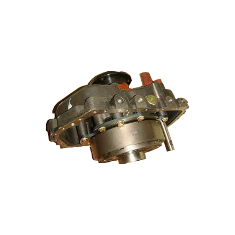
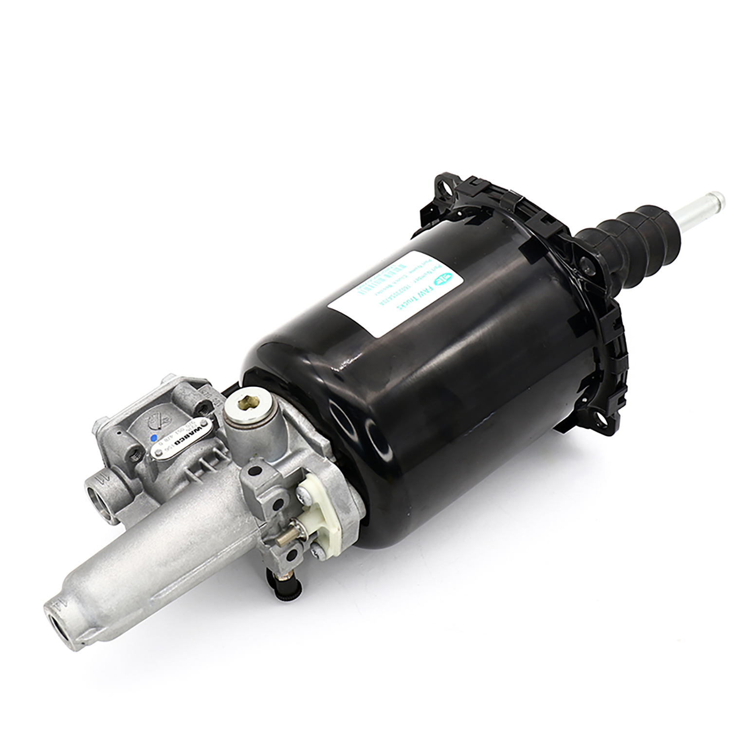


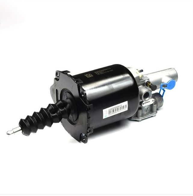
SINOTRUK® Genuine -Clutch booster- Spare Parts For SINOTRUK HOWO Part No.:WG9725230041
Basic information
JCHHR supply full range SINOTRUK, HOWO, HOWO PART, HOWO SPARE PARTS,STEYR, WEICHAI,WABCO, WABCO VALVES, WABCO BRAKE PART, SHACMAN, SHACMAN F2000 PARTS, SHACMAN F3000 PARTS, SINOTRUCK, SITRAK spare parts,professional service and good price
HOWO spare parts,HOWO dump truck parts,Original HOWO parts,HOWO truck parts,HOWO A7 truck spare parts,Genuine HOWO truck parts,Original HOWO spare parts,HOWO 371 truck spare parts,
HOWO part, HOWO tipper truck, HOWO 336, HOWO 371, HOWO concrete mixer, HOWO 70T,HOWO 70T mining truck parts, HOVA, HOVA 60, HOVA mining truck, HOVA parts, HOVA 60T, STEYR WD615,Original STEYR spare parts, STEYR 91 series, STEYR dump truck, STEYR WD618, WEICHAI,Original WEICHAI parts, Genuine WEICHAI part, WEICHAI spare parts, WEICHAI WD615, WEICHAI WP10, WEICHAI WP12, WD615,WD615 engine parts, WD615.47, WD615.69, WD615 336hp, WD615 371hp, WD618 diesel engine parts, WD618 420hp, D10 engine parts, D12 engine parts.

Specifications
|
PRODUCT NAME |
WG9725230041 |
OE NO. |
WG9725230041 |
BRAND NAME |
SINOTRUK Howo |
|
MODEL NUMBER |
WG9725230041 |
TRUCK MODEL |
WP10, WP12, WP6, WP7, WP5, WP4, WP3, WD615, WD618 |
PLACE OF ORIGIN |
Shandong, China |
|
SIZE |
Standard Size |
CERICATION |
CCC |
APPLICABLE |
Howo |
|
FACTORY |
CNHTC SINOTRUK |
TYPE |
BELT |
MOQ |
1pc |
|
APPLICATION |
ENGINE SYSTEM |
QUALITY |
High-Performance |
MATERUAK |
Rubber |
|
PACKING |
Standard Package |
SHIPPING |
By sea, By air |
PAYMENT |
T/T |
Relevant knowledge
Some trucks, especially medium and heavy trucks, have relatively high clutch pressure,
In order to reduce the force that the driver presses the clutch pedal,
Usually, a clutch booster, also known as a clutch booster cylinder or booster pump, is used,
This device uses both cylinders and cylinders.
What is the use of clutch booster cylinder
The clutch booster is used in cars with hydraulic operated clutch mechanisms. When the clutch is disengaged or engaged, this assembly is used to help increase output force. This assembly is installed between the clutch and the clutch master cylinder, without additional mechanical transmission components.
The working principle of clutch booster:
When the clutch pedal is pressed, hydraulic oil forms a certain amount of pressure in the clutch master cylinder and then enters the clutch booster. At this point, the hydraulic oil works in two steps in the booster. First, enter the hydraulic system of the clutch booster, where hydraulic oil acts on the hydraulic piston, which pushes the B rod forward. The left end of the hydraulic piston is sealed with a D-shaped rubber ring, and there are two hydraulic piston cups on the hydraulic piston to prevent oil leakage and sealing.
The other path flows to the clutch boost control valve system. When the hydraulic system is working, hydraulic oil pushes the relay valve. There are two cups on the piston of the relay valve, which not only withstand oil pressure but also serve as a seal. The piston of the relay valve moves to the left, overcoming the elasticity of the diaphragm return spring and the poppet valve spring. Close the exhaust port, open the lift valve, and the compressed air enters the power cylinder. Overcoming the force of the return spring of the power cylinder, it works with the A and B push rods to push the piston to the right. At this point, the combination of oil pressure and air pressure simultaneously serves as a boost. In the absence of compressed air in the car cylinder, the hydraulic system of the booster can also operate independently, but it is more laborious to operate.
The master cylinder and slave cylinder of the clutch are actually equivalent to two independent hydraulic cylinders. The master cylinder has inlet and outlet oil pipes, while the slave cylinder only has one. When the clutch is pressed, the pressure from the master cylinder passes through the slave cylinder, which starts working. Then, the release fork separates the clutch pressure plate and pressure plate from the flywheel, and gear shifting can begin. After releasing the clutch, the slave cylinder will stop working, and the clutch pressure plate and pressure plate will come into contact with the flywheel again. Power will continue to be transmitted, and the oil from the slave cylinder will return. In order to enable the driver to perceive the degree of clutch engagement and disengagement at any time, an increasing function is formed between the output force of the car's clutch pedal and the pneumatic booster. When the pneumatic power system fails, it can also ensure that the driver can manually operate the clutch.