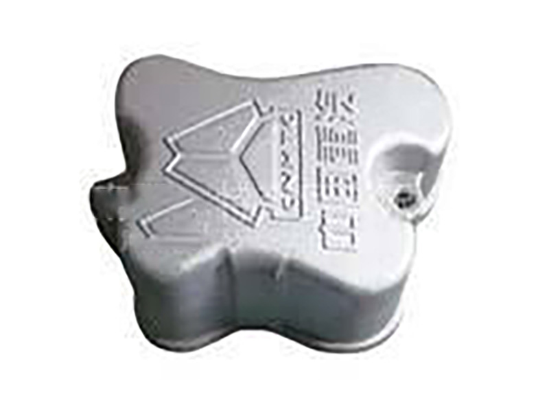
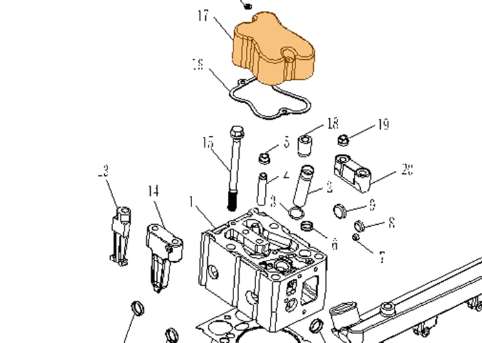
SINOTRUK® Genuine – Cylinder Head Cover – Engine Components For SINOTRUK HOWO WD615 Series Engine Part No.: VG14040065
Basic information
JCHHR supply full range SINOTRUK, HOWO, HOWO PART, HOWO SPARE PARTS,STEYR, WEICHAI,WABCO, WABCO VALVES, WABCO BRAKE PART, SHACMAN, SHACMAN F2000 PARTS, SHACMAN F3000 PARTS, SINOTRUCK, SITRAK spare parts,professional service and good price
HOWO spare parts,HOWO dump truck parts,Original HOWO parts,HOWO truck parts,HOWO A7 truck spare parts,Genuine HOWO truck parts,Original HOWO spare parts,HOWO 371 truck spare parts,
HOWO part, HOWO tipper truck, HOWO 336, HOWO 371, HOWO concrete mixer, HOWO 70T,HOWO 70T mining truck parts, HOVA, HOVA 60, HOVA mining truck, HOVA parts, HOVA 60T, STEYR WD615,Original STEYR spare parts, STEYR 91 series, STEYR dump truck, STEYR WD618, WEICHAI,Original WEICHAI parts, Genuine WEICHAI part, WEICHAI spare parts, WEICHAI WD615, WEICHAI WP10, WEICHAI WP12, WD615,WD615 engine parts, WD615.47, WD615.69, WD615 336hp, WD615 371hp, WD618 diesel engine parts, WD618 420hp, D10 engine parts, D12 engine parts.


Specifications
|
PRODUCT NAME |
VG14040065 |
OE NO. |
VG14040065 |
BRAND NAME |
SINOTRUK Howo |
|
MODEL NUMBER |
VG14040065 |
TRUCK MODEL |
WP10, WP12, WP6, WP7, WP5, WP4, WP3, WD615, WD618 |
PLACE OF ORIGIN |
Shandong, China |
|
SIZE |
Standard Size |
CERICATION |
CCC |
APPLICABLE |
Howo |
|
FACTORY |
CNHTC SINOTRUK |
TYPE |
BELT |
MOQ |
1pc |
|
APPLICATION |
ENGINE SYSTEM |
QUALITY |
High-Performance |
MATERUAK |
Rubber |
|
PACKING |
Standard Package |
SHIPPING |
By sea, By air |
PAYMENT |
T/T |
Relevant Knowledge
Maintenance steps for cylinder head: inspection and disassembly
Cylinder head inspection method
"How to maximize the power of a diesel engine depends on the sealing effectiveness of the new cap. This requires that the surface fineness of the cap be very high, at least reaching level 6 or higher. However, as the diesel engine grows in service time, after frequent force shocks, small deformations will occur as the use time increases, which requires that the flatness of the cap be accurately checked during overhaul.", If the unevenness reaches above 0.10 mm, it is necessary to use a dedicated grinding machine for surface grinding, but the grinding amount should not be too large to avoid affecting the compression ratio of the engine and affecting its working performance. There should be no cracks between the holes. These cracks are not visible during repair, and flaw detection should be conducted during overhaul of the cylinder head.
1. Cylinder head stria sound detection
Generally speaking, cracks are prone to occur in the plane of the cylinder block, valve guide holes, fuel injection exposed holes, and cooling water jacket walls. Inspection can be carried out by hydraulic test, pneumatic test, magnetic flaw detection, and other methods.
2. Cylinder head flatness inspection
If there are scars, corrosion, or uneven wear on the mating surface of the disordered cover and the cylinder gasket, it should be inspected. The flatness should be checked with a straight edge and a feeler gauge. Each machining amount with the cylinder liner should be 0.1270~0.1524mm. When the thickness of the disordered cover reaches the reasonable usage limit, it should be carefully discarded. The minimum thickness of the Tangmingqi 56BT series diesel engine cover is 11.00m01, the maximum is 111.25m, and the limit is 110.240101. It should be noted that when the surface of the disordered cover is not reworked, Only 0.7939mm cylinder pads are allowed. The thickness X of the cylinder head of KTTA diesel engine shall not be less than 119.76mm.
The upper and lower planes of the cylinder head must be parallel, with an unevenness of within 0.13mm, otherwise the cylinder liner seat hole may be deformed.
3. Check cylinder pressure
The engine oil temperature should not be lower than 30% C when checking the cylinder pressure. The steps for detecting the cylinder pressure are as follows: (1) Close the start switch, fully open the throttle, and use the cylinder pressure tester V.A.G1381/V.A.G1763 to detect the compression pressure. (2) Start the starter until the pressure value displayed on the tester no longer increases.
2、 Removal and installation of cylinder head
When repairing the cylinder head, the relevant seals, gaskets, self-locking nuts, and bolts with specified tightening torque must be replaced. When installing the face cover with a camshaft, the contact surface between the tappet and the cam must be moistened with engine oil. The plastic protective sleeve of the cylinder must be removed before installing the valve. When installing a new cover or cylinder head gasket, the old coolant must be drained and then filled with new coolant. Cylinder heads with cracks between the valve seats can still be used if the maximum width of the cracks does not exceed 3mm, without affecting their service life.
1. Disassembly and assembly of intake manifold
(1) Removal of the intake manifold.
Before disassembly, check the car radio password, turn off the ignition, disconnect the battery ground wire, drain the coolant, and when removing the intake manifold, disconnect or cut all cables and cables. During installation, it must be reset as is. Intake manifold
The pipe and disassembly steps are as follows:
D Remove the coolant expansion tank and hose.
Remove the throttle cable at the throttle control unit and the bracket (without removing the throttle cable clamp), remove the air hose at the throttle control unit, disconnect the vacuum pipe toward the activated carbon, and pull out the vacuum pipe toward the brake booster.
@Remove the intake air temperature sensor and throttle control unit plugs, and then pull out the plugs from the hall sensor receiver
Remove the fuel manifold fastening bolts and pull the vacuum pipe away from the fuel pressure regulator. Remove the fuel manifold with fuel injector from the intake pipe and place it on a clean cloth behind the engine compartment. 6 Remove the coolant hose from the upper coolant pipe. Remove the lower coolant pipe fastening bolts from the intake manifold and coolant pipe flange at the rear of the cylinder head. Remove the crankcase ventilation hose at the intake manifold, remove the intake manifold bracket, pull out the oil scale, unscrew the intake manifold fastening bolts at the flange, and fold off the intake manifold. Use a clean cloth to cover the air inlet on the air chaos cover. (2) Installation of the intake manifold.
Replace the gasket and seal, and install the intake manifold in the reverse order of removal. During installation, pay attention to adjusting the throttle cable and filling in coolant. After installation, pay attention to the following operations: D After connecting the battery, enter the radio anti-theft password,
@Fully close the front door power window with the power switch. Operate all electric door and window switches in the closed direction (at least 1s) to activate the one-touch function.
3 Adjust the clock.
4. Perform the matching of throttle control components.
2. Disassembly and assembly of cylinder head
(1) Disassembly steps of cylinder head cover:
D Remove the peripheral components of the engine cylinder head.
Unscrew the fastening bolts of the crankcase ventilation pipe at the heat insulation and cylinder head positions, and gently move the crankcase ventilation pipe to one side
S Remove the upper guard of the timing belt.
Unplug the ignition coil plug, disconnect the ground wire, and unscrew the ignition coil fastening bolt.
Unscrew the cylinder head cover nut and remove the cylinder head cover.
(2) Install the cylinder head in the reverse order of removal. Special attention should be paid during installation: If the cylinder head gasket is damaged, it should be replaced.
3. Maintenance of cylinder head
(1) Disassembly steps of cylinder head:
D Check the car radio password. Turn off the ignition switch and disconnect the battery ground wire. Drain the coolant
Unplug the fuel delivery pipe and return pipe on the fuel distribution pipe. When removing, pay attention to the pressure in the fuel system. After removing, close the pipe to avoid polluting the fuel system. Remove the exhaust manifold and 2-way catalytic converter from the intake manifold.
Remove the plugs of the activated carbon canister solenoid valve, ignition power terminal stage, and air quality meter in order.
Unplug the hose connector and remove the air filter housing. Pull off the plug on the ignition coil and the plug on the coolant temperature sensor dew point. Open the clamps for all lines from the cylinder head and set the wires aside. Pull out the coolant hose leading to the heat exchange at the rear of the gas cap (first loosen the holder on the connecting flange). Remove the upper guard of the timing belt, turn the crankshaft in the direction of engine rotation through the central bolt on the crankshaft timing belt pulley, and adjust the crankshaft to the top dead center position of the first cylinder
Loosen the timing belt tensioner with a T45 screwdriver, press down on the timing belt tensioner, remove the timing belt from the camshaft timing pulley, unscrew the Torx bolt, and swing the tensioning plate forward. O Remove the cylinder head cover
Unscrew the cylinder head bolts and remove the cylinder head
(2) Inspection of cylinder head
Measure the cylinder head with a straight edge or a thickness gauge, and the maximum allowable deformation is 0.1mm. As shown in Figure 3, the cylinder head trimming (scraping) dimension should not exceed the minimum dimension a, and the minimum dimension a=139.25mm


